Technical Diagnosis
DC/Solar Battery Charger
Part No. IDC25 / IDC45
Before beginning your diagnosis
We recommend scrolling down and familiarising yourself with our diagnosis checklist and key measurement values.
A multimeter and an understanding of how to use it, is crucial for an accurate fault diagnosis of your IDC25/IDC45. You will need to be able to check voltages, current and continuity.
Select which LED indicators are active
When your Projecta DC/Solar Battery Charger is installed and operating correctly, the Charging, Solar and Alternator LED indicators will be a solid green.
To diagnose your fault, select the one of the LED indicators in the tabs above.

LED Indicator
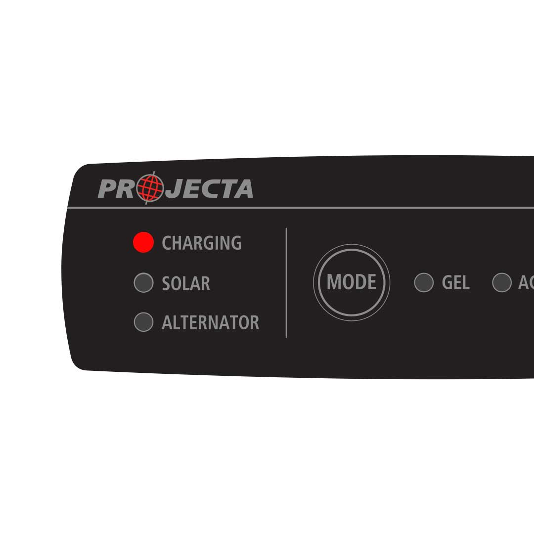
Charging = Solid Red
Fault
The unit is faulty
Remedy
Check if there is any output from the BROWN wire WHILE CONNECTED to the AUX battery.
Action
Using your multimeter, check the voltage of the AUX battery before engaging the IDC25/IDC45. Make a note of the voltage and then engage the IDC25/IDC45 (start the vehicle engine or connect solar). Wait 2 minutes then check the AUX battery again. If it is higher than the initial measurement, the IDC25/IDC45 is most likely charging. Contact Projecta Technical Support on 1800 422 422
LED Indicator
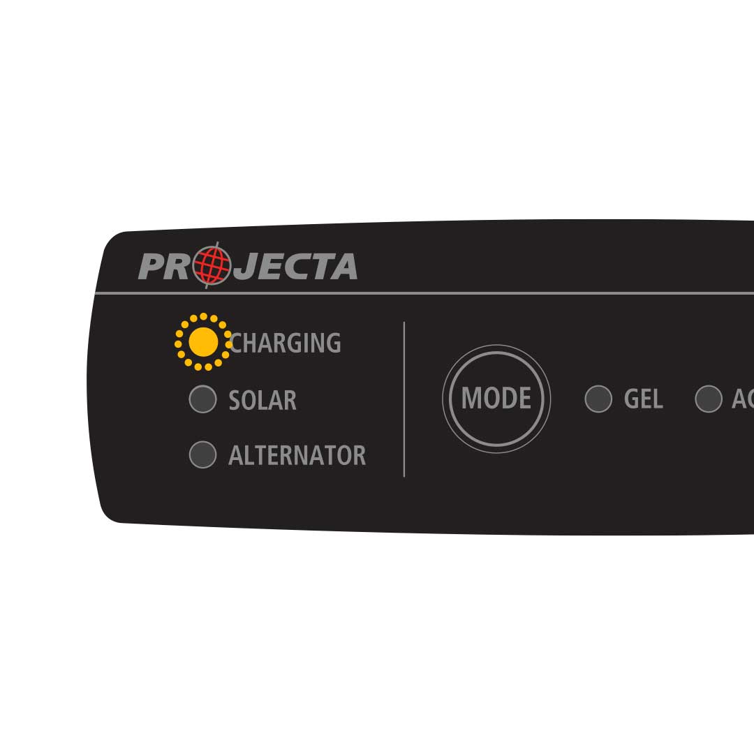
Charging = Flashing Amber
Fault
Bulk Charging Time Out
Remedy
AUX battery may be faulty or current draw from the battery is too high for an extended period (or output is limited).
Action
Batteries do not last forever! To eliminate a faulty battery as a possible cause, it is recommended to have the battery load tested to ensure the battery is capable of accepting/holding a good charge. If the Charging LED flashes AMBER, the IDC25/IDC45 has given up trying to charge your battery due to the batteries inability to accept or maintain the charge. Temperature sensing wire may have been cut!
LED Indicator
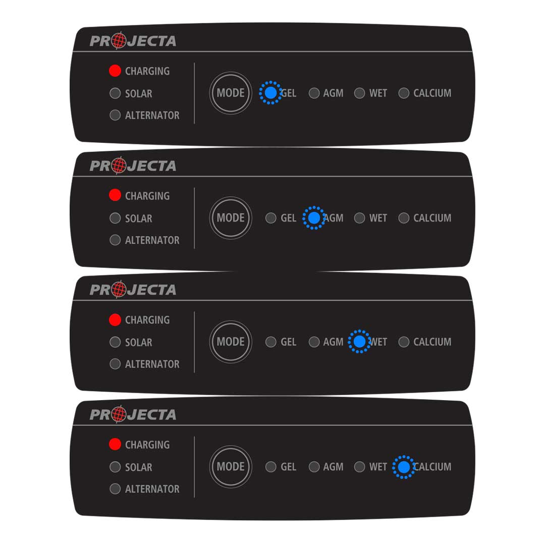
Charging = Solid Red
Battery Type = Flashing Blue
Fault
Output battery is reverse connected
Remedy
Check polarity of output cable. BROWN is positive and should be connected to the POSITIVE terminal on the AUX battery
Action
Check the BROWN output cable is connected to the POSITIVE terminal on the AUX battery and the NEGATIVE terminal is grounded to the same point as the HEAVY BLACK negative cable on the IDC25/IDC45. Simply connect the IDC25/IDC45 BLACK CABLE to the AUX battery NEGATIVE post, then the NEGATIVE cable from the starter battery to the same NEGATIVE TERMINAL on the AUX battery.
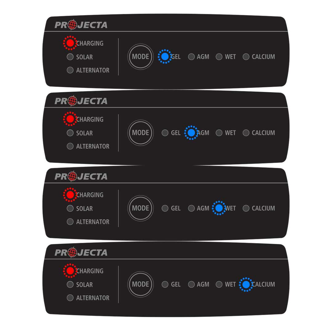
LED Indicator
Charging = Flashing Red
Battery Type = Flashing Blue
Fault
Over-voltage detected at output (BROWN cable)
Remedy
Check the AUX battery voltage
Action
Check there is no additional charging device that is feeding the AUX battery, particularly SOLAR. If there is, the voltage MUST be lower than 16.0 volts. Try removing the additional charge source (solar?) and check if the charger operates correctly
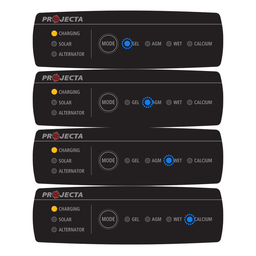
LED Indicator
Charging = Solid Amber
Battery Type = Flashing Blue
Fault
Output open circuit due to blown fuse or flat battery
Remedy
Check polarity of output cable. BROWN is positive and should be connected to the POSITIVE terminal on the AUX battery
Action
Check the BROWN output cable is connected to the POSITIVE terminal on the AUX battery and the NEGATIVE terminal is grounded to the same point as the HEAVY BLACK negative cable on the IDC25/IDC45. Best to simply connect the IDC25/IDC45 BLACK CABLE to the AUX battery NEGATIVE post, then the NEGATIVE cable from the starter battery to the same NEGATIVE TERMINAL on the AUX battery.
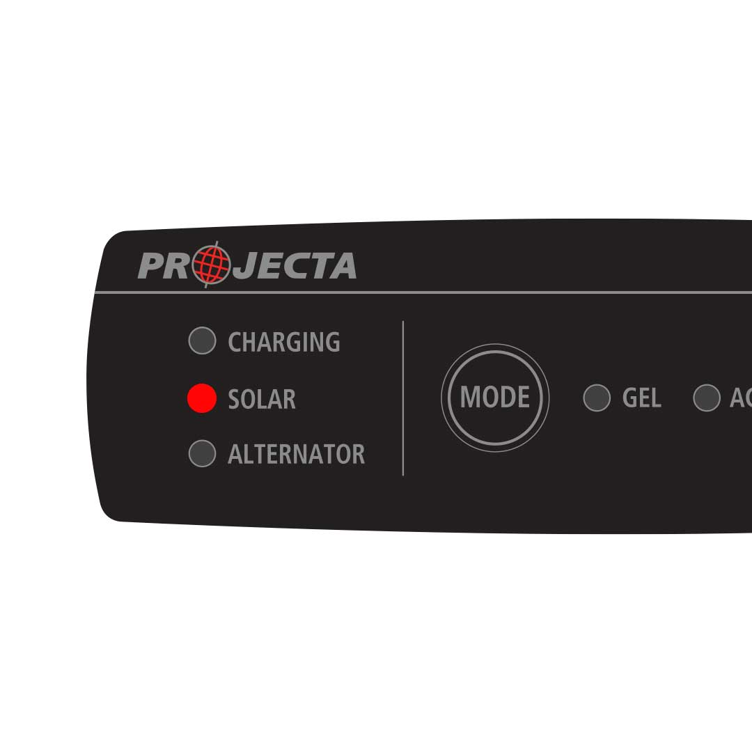
LED Indicator
Solar = Solid Red
Fault
Solar input is reverse connected
Remedy
Check the Solar input polarity is correct
Action
Solar panels’ cable polarity is not always clear. Check the cable connections to ensure the POSITIVE solar output cable is connected to the GREEN solar input cable. Also check the fuse if fitted.
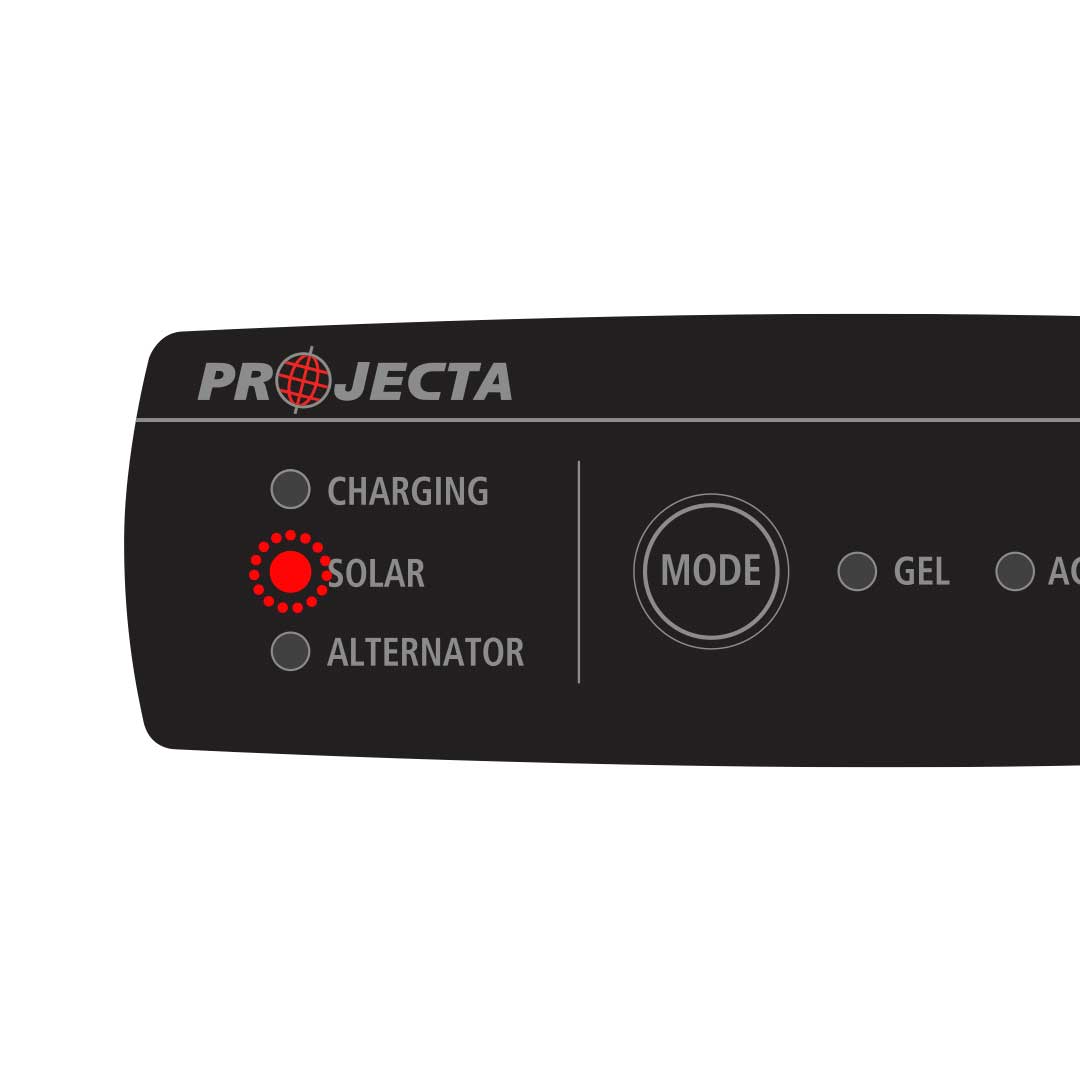
LED Indicator
Solar = Flashing Red
Fault
Over-voltage detected at Solar Input (GREEN Cable)
Remedy
Check the Solar panel open circuit voltage
Action
Some solar panels (particularly those that are intended from domestic solar installations) output voltages higher than the IDC25/IDC45 max voltage of 28.0 volts. Any higher and you will see this error pattern and you may need to consider an alternative panel.
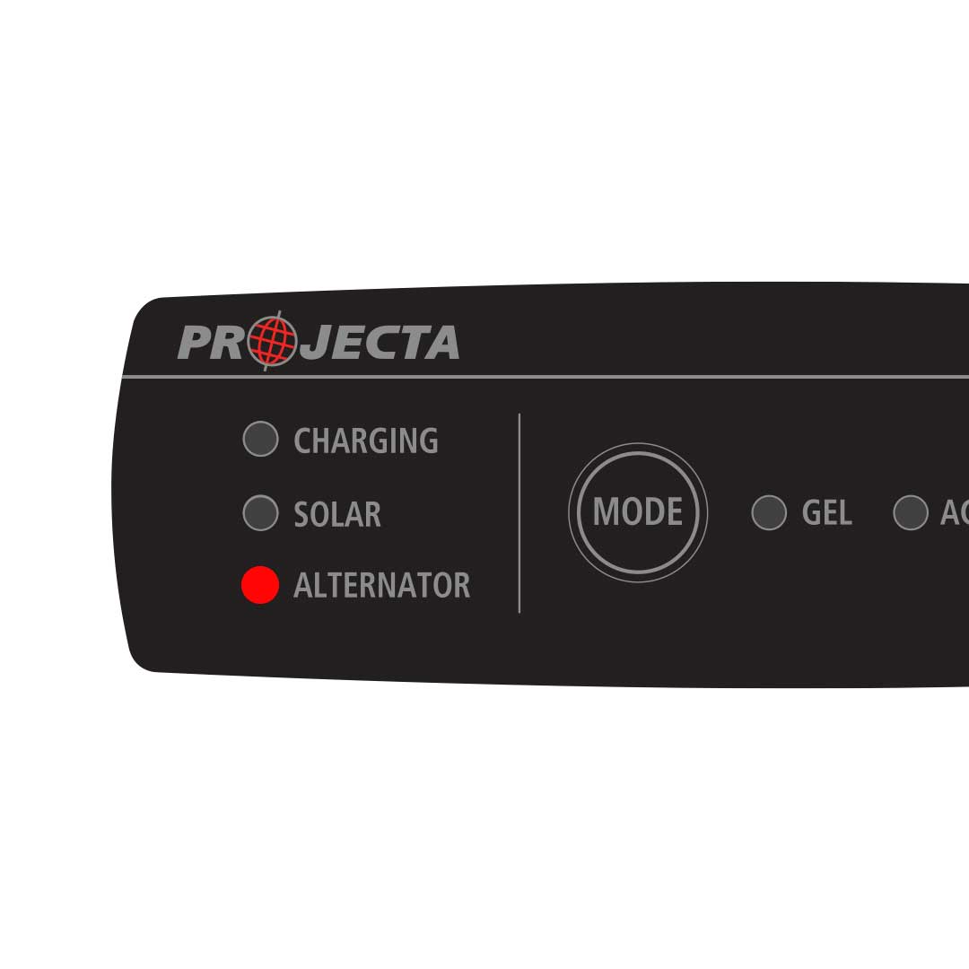
LED Indicator
Alternator = Solid Red
Fault
Alternator Input is reverse connected
Remedy
Check alternator input connection. The RED cable on the IDC is POSITIVE.
Action
Ensure the POSITIVE from the starter battery is feeding the RED input wire on the IDC25/IDC45. If the issue persists, use your multimeter and check the polarity of your Anderson connector (if fitted).
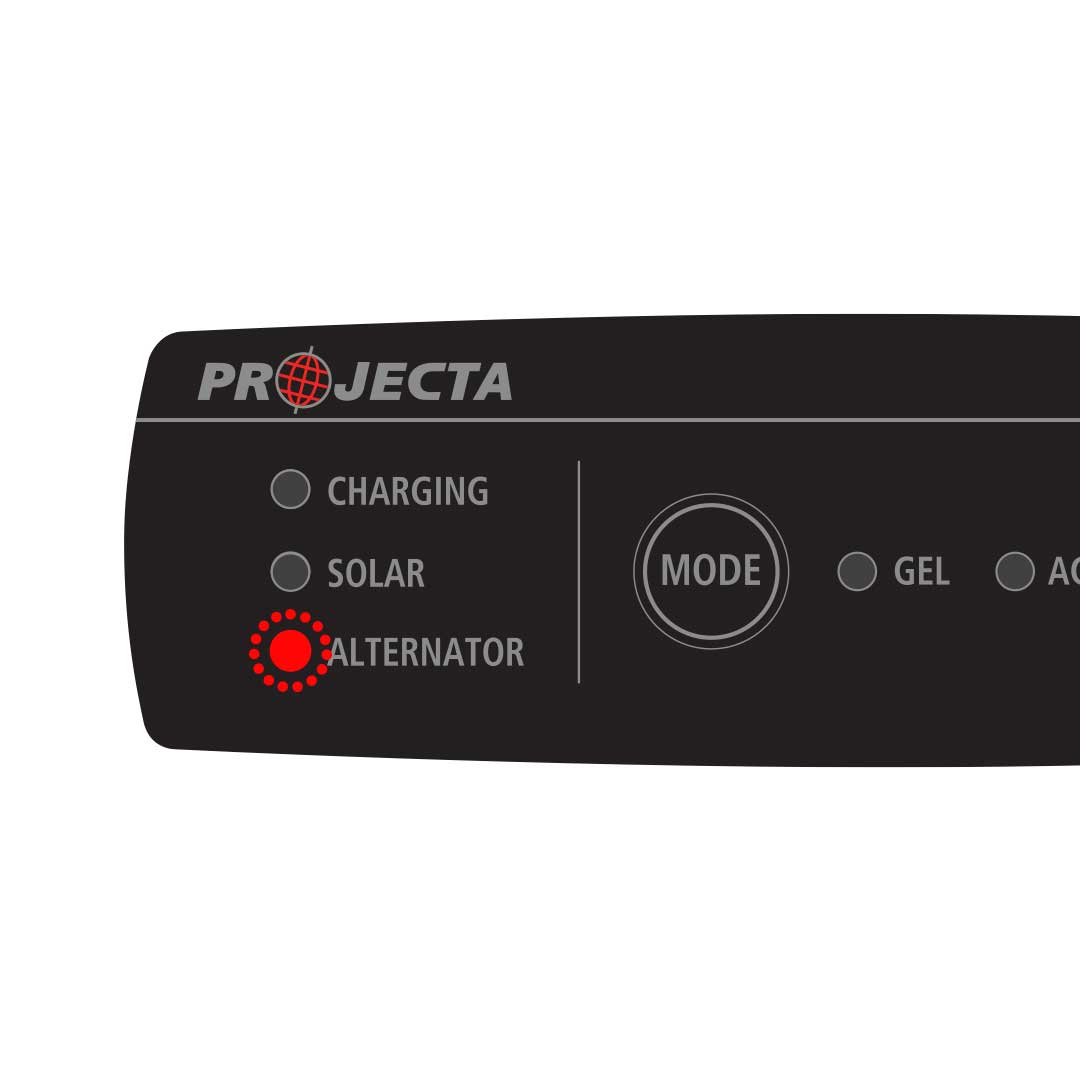
LED Indicator
Alternator = Flashing Red
Fault
Over voltage is detected at alternator.
Remedy
Check voltage at the starter battery.
Action
Check there is no additional charging device that is feeding the STARTER battery such as unregulated SOLAR. The voltage MUST be less than 32 volt. Check the alternator voltage at the Starter Battery BEFORE starting the engine and then again with the engine running.
Diagnosis Checklist
Before you begin your fault diagnosis, there are a few things to remember about your DC Solar Charger (IDC25/IDC45) and your wiring installation:
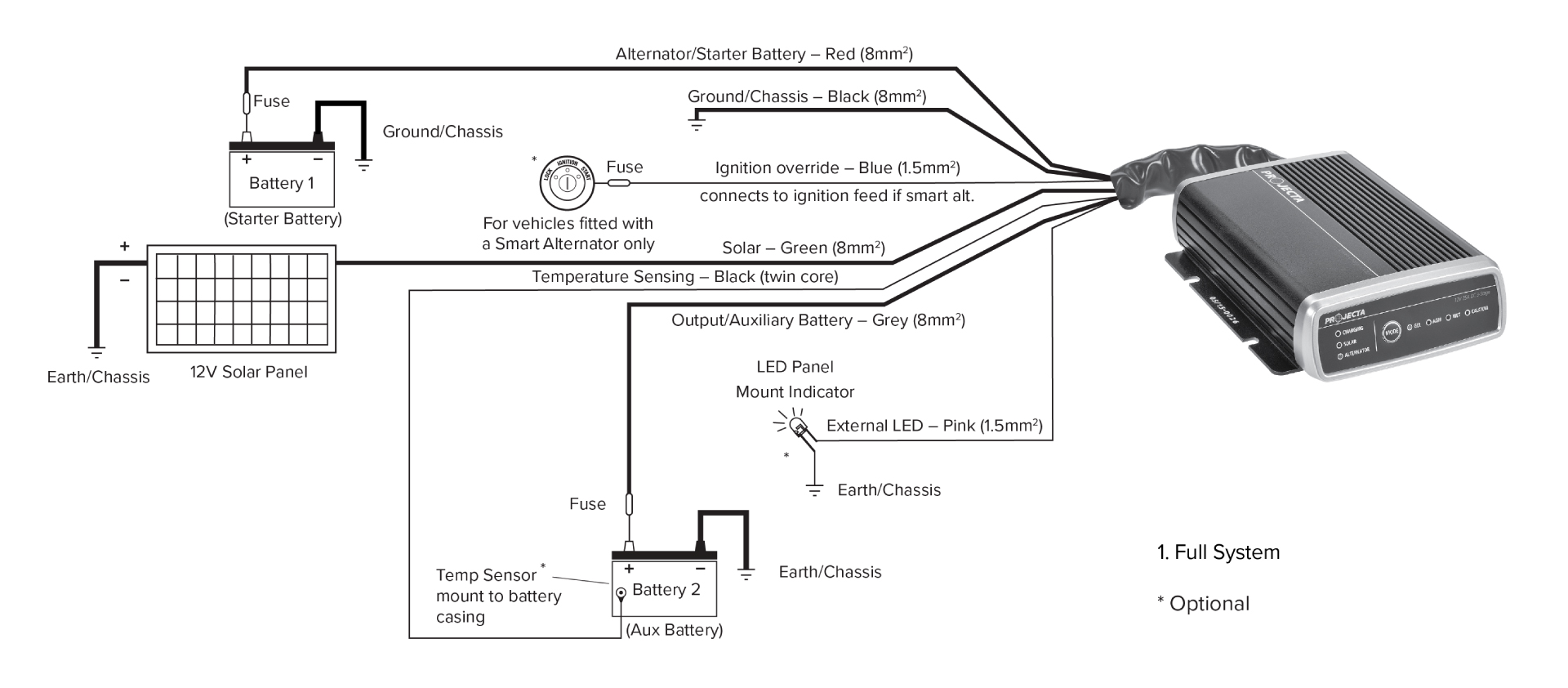
- If your vehicle has a smart alternator (variable output voltage) you must connect the BLUE WIRE to a source that is active ONLY when the ignition is ON.
- The BLUE “ignition sense” wire will activate the IDC25/IDC45 ON when there is greater than 12.2 volts applied. You must ensure there is NO VOLTAGE available to the BLUE WIRE when the ignition is turned OFF
- The BLUE “ignition sense” wire is ONLY required if the IDC25/IDC45 voltage feed is less than 13.4 volts CONSISTENTLY.
- Starter battery Negative, AUX battery negative, Solar Negative and IDC25/IDC45 Negative MUST all “SEE” each other either through a common point or at least are all connected to the same METAL surface.
- The first thing to check when you are experiencing issues, are the FUSES. There should be a 50 amp fuse on the INPUT (RED) and OUTPUT (BROWN) cables.
- It is highly recommended NOT to use Circuit Breakers. Incorrect fitting or vibration can cause intermittent operation. We recommend ANS fuses or better.
- Ensure THOROUGH cleaning of both sides of metal surfaces when grounding the NEGATIVE cables to the chassis. In our experience, this issue generates the majority of our request for support calls.
- Consider good quality STAR or SPRING washers when bolting to the CHASSIS for grounding to ensure the best contact to the chassis. Do not underestimate the impact of inadequate grounding.
- DO NOT use self tapper screws for grounding high current cables to the chassis. Immediate failure or failure over time is almost certain. Use a bolt and nut, and tighten firmly.
- The IDC25/IDC45 solar input (GREEN cable) must NOT have a Solar Controller installed between the Solar Panel and the IDC25/IDC45. Only a raw feed from the solar panel is suitable.
- It is NORMAL for the IDC25/IDC45 to appear to be idle every 2 minutes while the unit searches for the best mode of operation.
- An intermittent charge light suggests a high voltage drop from the alternator (inadequate grounding or low voltage to the red input wire).
Key Measurement Values
A multimeter is critical for accurate diagnosis of IDC25 issues, plus an understanding of how to use it. You need to be able to check voltages, current and continuity.
| Measurement Values | 12V Vehicle | 24V Vehicle |
|---|---|---|
| Minimum Input Voltage (From Starter Battery) | 11.9V | 26.8V |
| Maximum Input Voltage (From Starter Battery) | 32.0V | 32.0V |
| Maximum Solar Voltage Input | 28.0V | 28.0V |
| Maximum Solar Wattage | 385W | 385W |
| IDC25 Turn On Voltage (Blue Wire Not Connected) | 13.4V | 26.8V |
| IDC25 Turn Off Voltage (Blue Wire Not Connected) | 12.8V | 25.6V |
| IDC25 Turn On Voltage (Blue Wire Is Connected) | 12.2V | 24.4V |
| IDC25 Turn Off Voltage (Blue Wire Is Connected) | 11.9V | 24.0V |
Typical DC Charger Wiring Installation
